EG500 CE/FCC/ROHS/RCM Certificates Approved
December 20, 2022EG324 CE FCC Certification Approved
March 23, 2023About CODESYS
CODESYS is a leading manufacturer-independent IEC 61131-3 integrated automation software development environment for programming controller applications.
In this demo we will use Codesys Development System V3 software as IDE to config and program a project running on Elastel EG500 and EG410, to trigger a lamp on and off via DO port on device.
The conclusion is, the CODESYS is perfect compatible with Elastel Industrial Raspberry Pi products.
ELASTEL Industrial Raspberry Pi
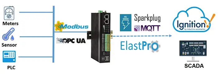
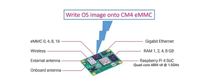
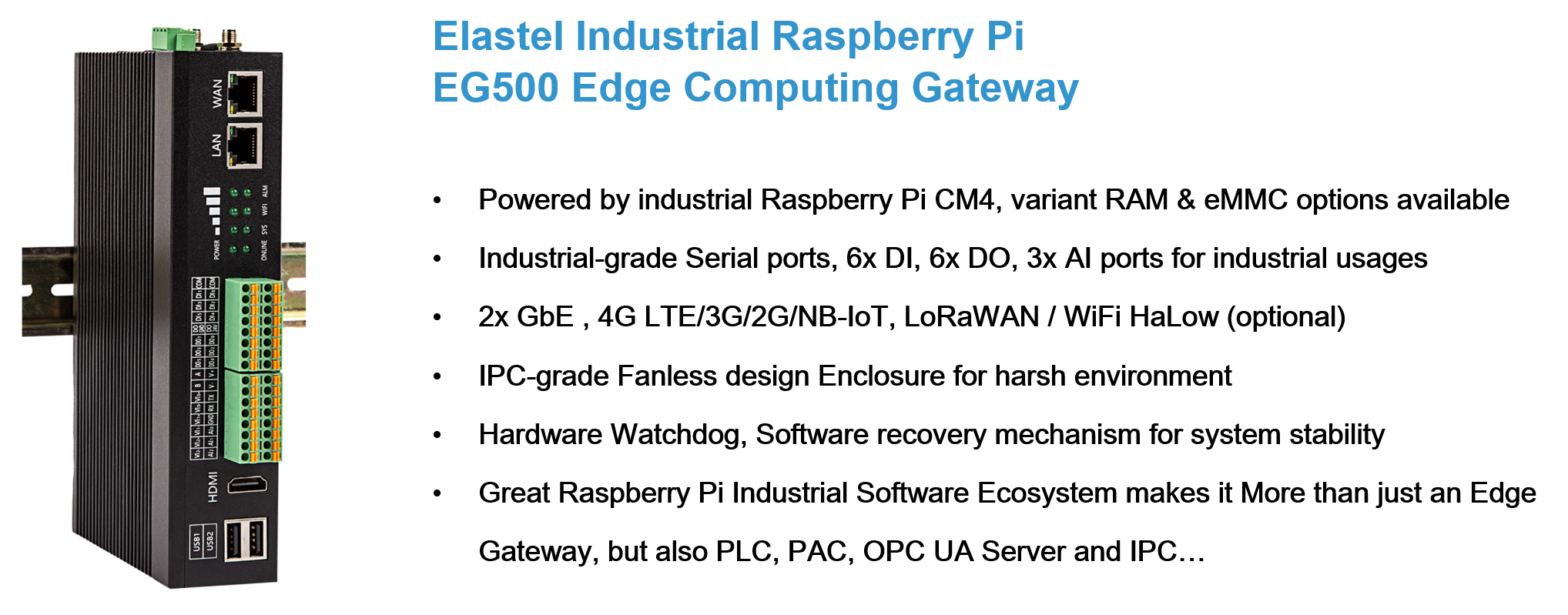
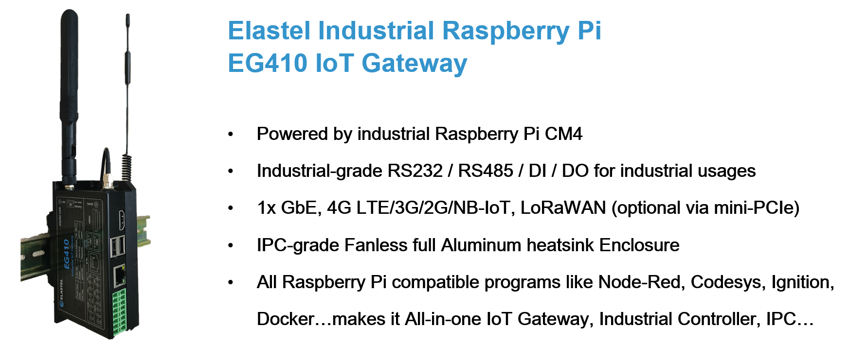
Powered by Raspberry Pi CM4, Designed as high-scalability and rugged industrial-grade hardware, rich I/O and connectivity options , and with the great Raspberry Pi software ecosystem compatibility, Elastel industrial Raspberry Pi series EG500 and EG410 are perfect as Edge Computer, IoT Gateway, Industrial Controller… for any kinds of your IIoT applications.
Featured Products
Prerequisites
- 1 x Windows PC Host computer
- 1 x Elastel industrial Raspberry Pi EG500 or EG410
- CODESYS Development System V3 Software
- CODESYS Control for Raspberry Pi MC SL, You may need purchase the License for commercial purpose
Please visit the CODESYS Development System V3 download page to download the CODESYS Development System V3 software according to your Windows PC Host computer, setup and follow the installation wizard to install the program.

Getting Started
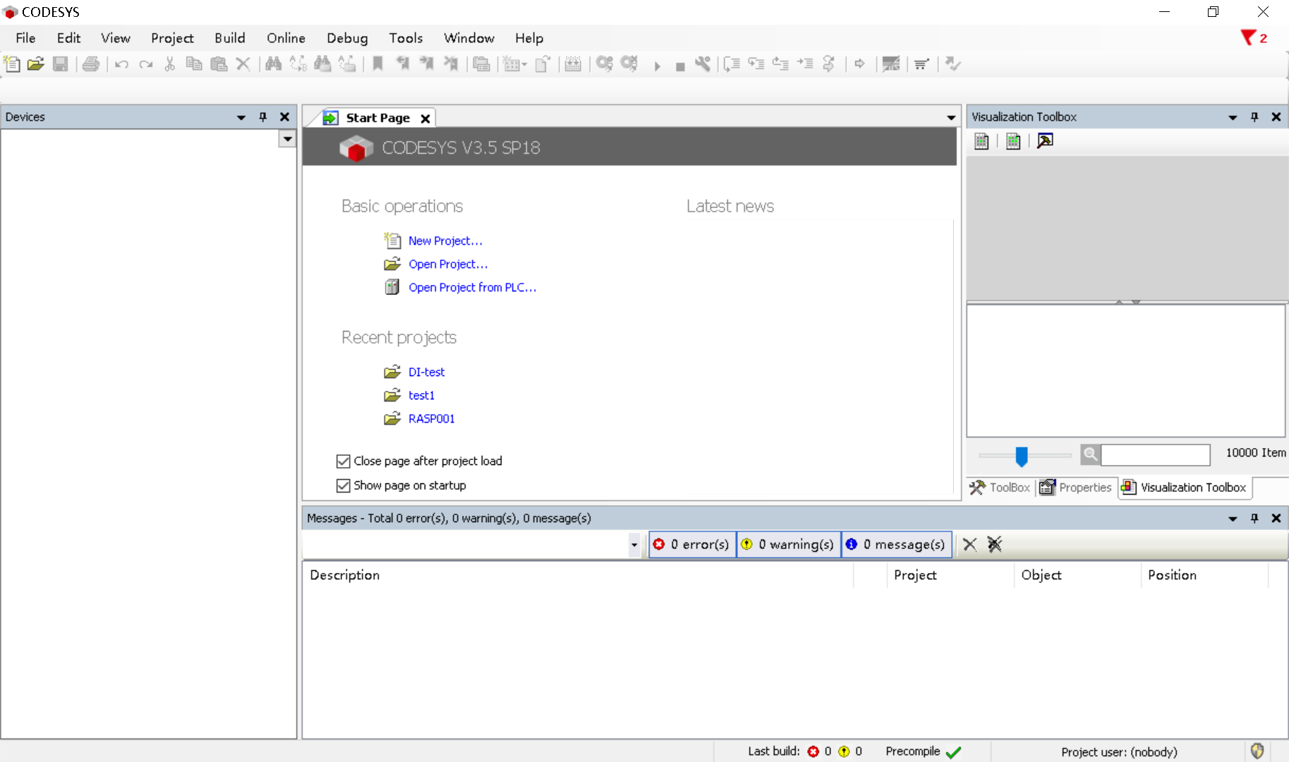
1. Install packages on CODESYS IDE
- 1.1 Run the CODESYS Development System V3 software, and install the relevant software packages in CODESYS Installer.
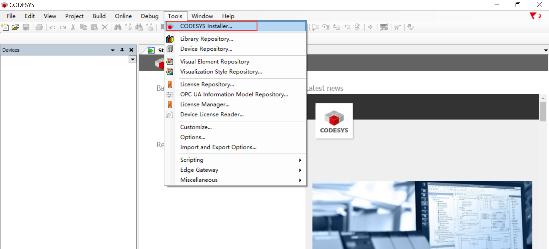
Open the CODESYS Installer by click on “Tools> CODESYS Installer…”
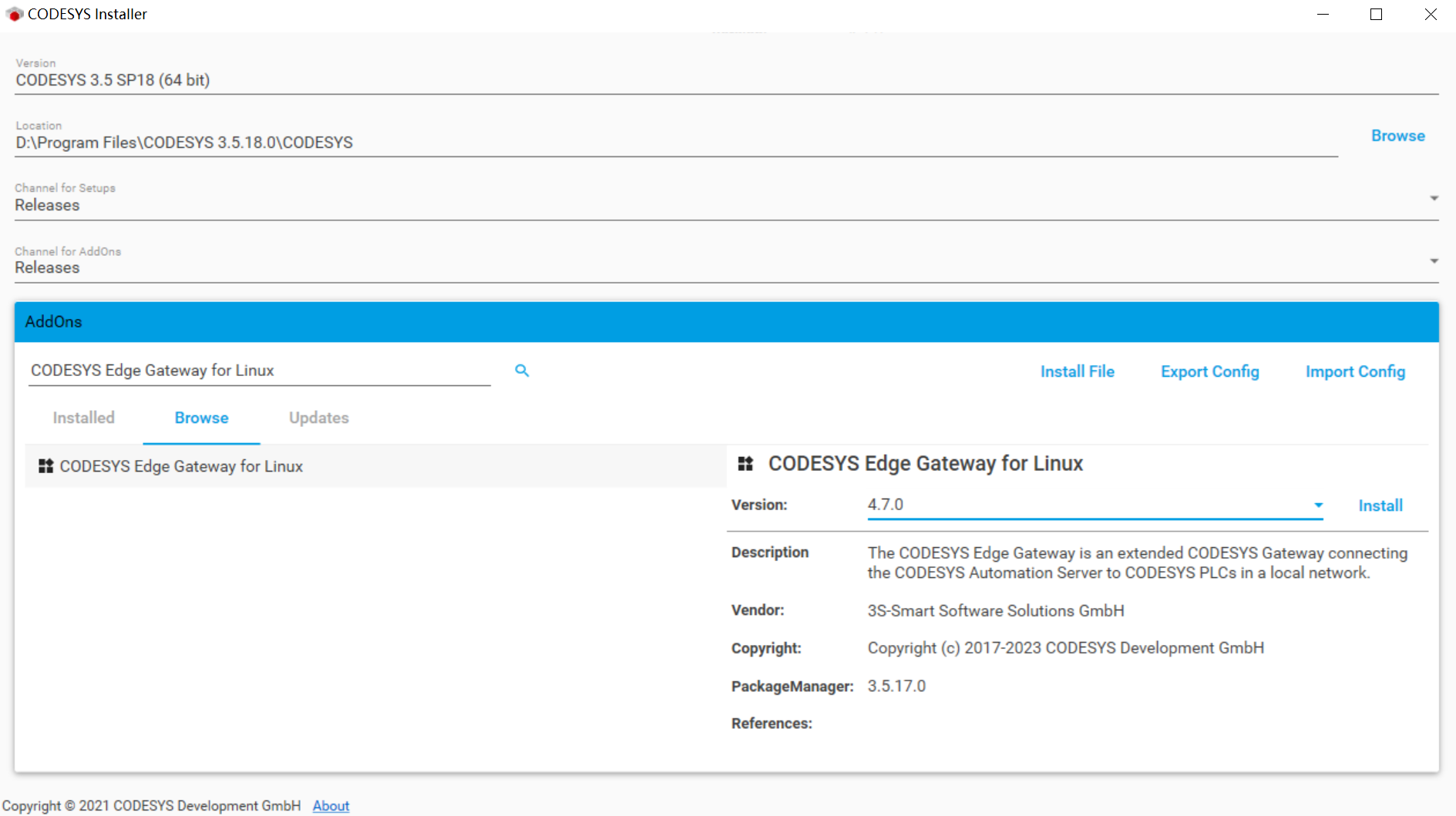
- 1.2 Install “CODESYS Edge Gateway for Linux” package.
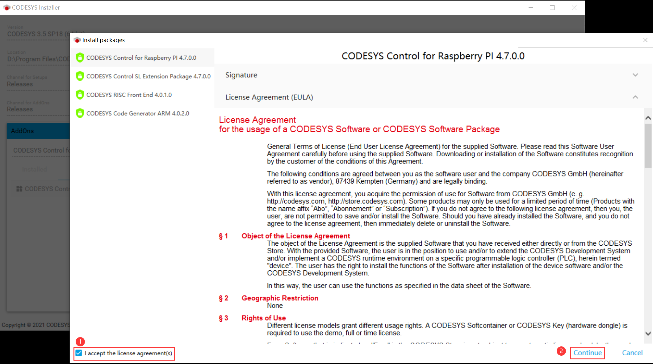
Click “Browse” and search “CODESYS Edge Gateway for Linux”, then Install it after “accept the license agreements”
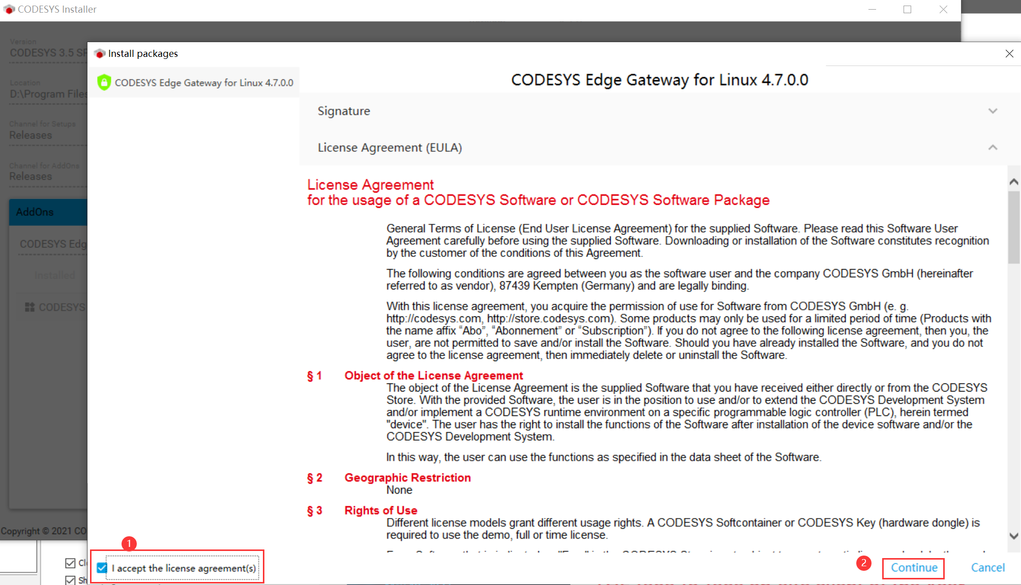
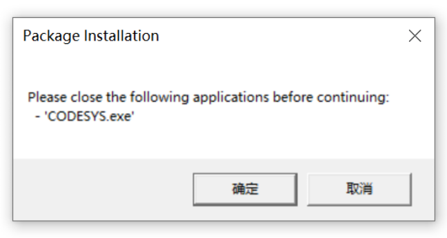
Note, you may need close CODESYS Development System V3 software as required during package installation, otherwise you will get warning as below:
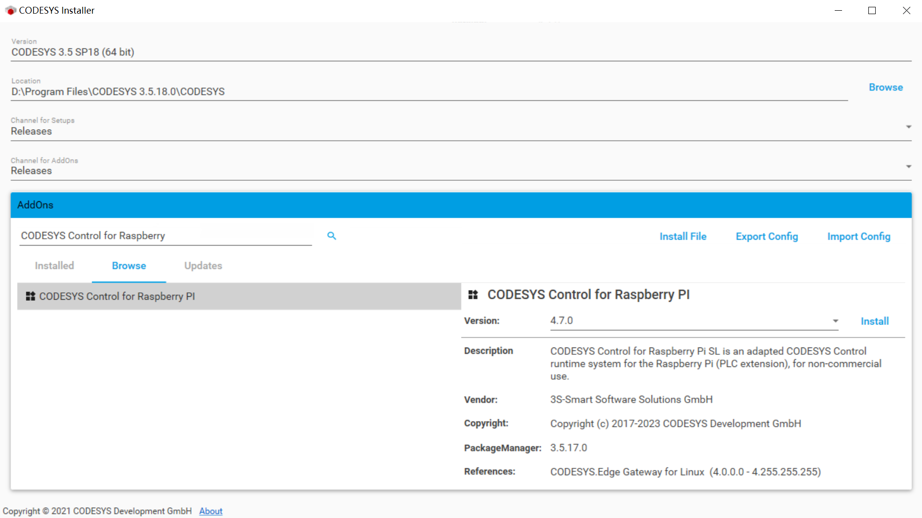
- 1.3 Install “CODESYS Control for Raspberry” package.
Click “Browse” and search “CODESYS Control for Raspberry” and Install it after “accept the license agreements”
2. Configure and Install CODESYS on EG500
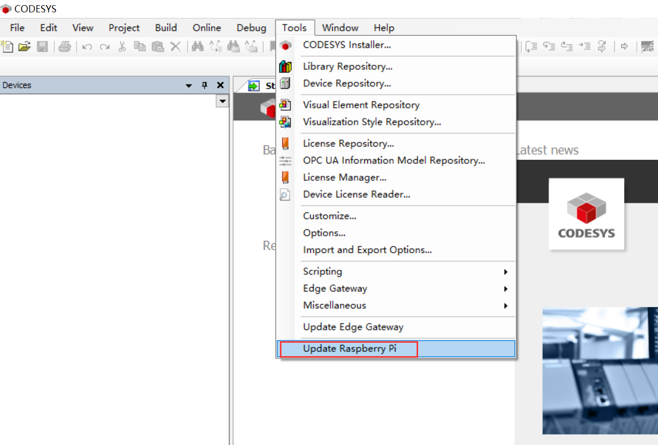
- 2.1 Select menu “Tools>Update Raspberry Pi”
- 2.2 Fill-in the Login credentials at the Raspberry Pi side panel, then click the “Scan” button to scan the available Raspberry Pi devices list, select the one you are setting.
Click the “Install” button to install the “CODESYS Control for Raspberry Pi runtime” package into EG500.
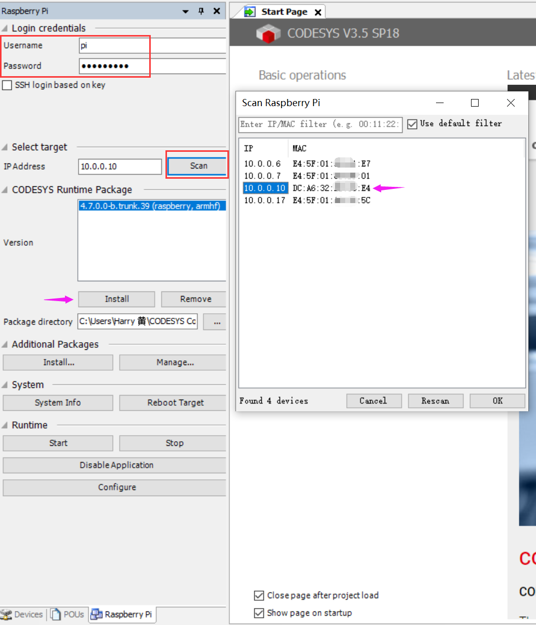
Login credentials
Username: pi
Password: raspberry
Select Target:
IP Address: 10.0.0.10 ## (in this demo, the EG500 IP is 10.0.0.10, while EG410 is 10.0.0.16)
CODESYS Runtime Package:
Version: 4.7.0.0-b.truck.39 (raspberry, armhf)
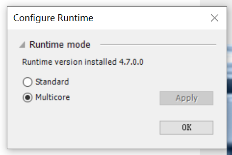
- 2.3 At the pop-up window “Configure Runtime”, select the “runtime mode” according to your preferences, in this case we choose the default “Multicore” and click “OK”
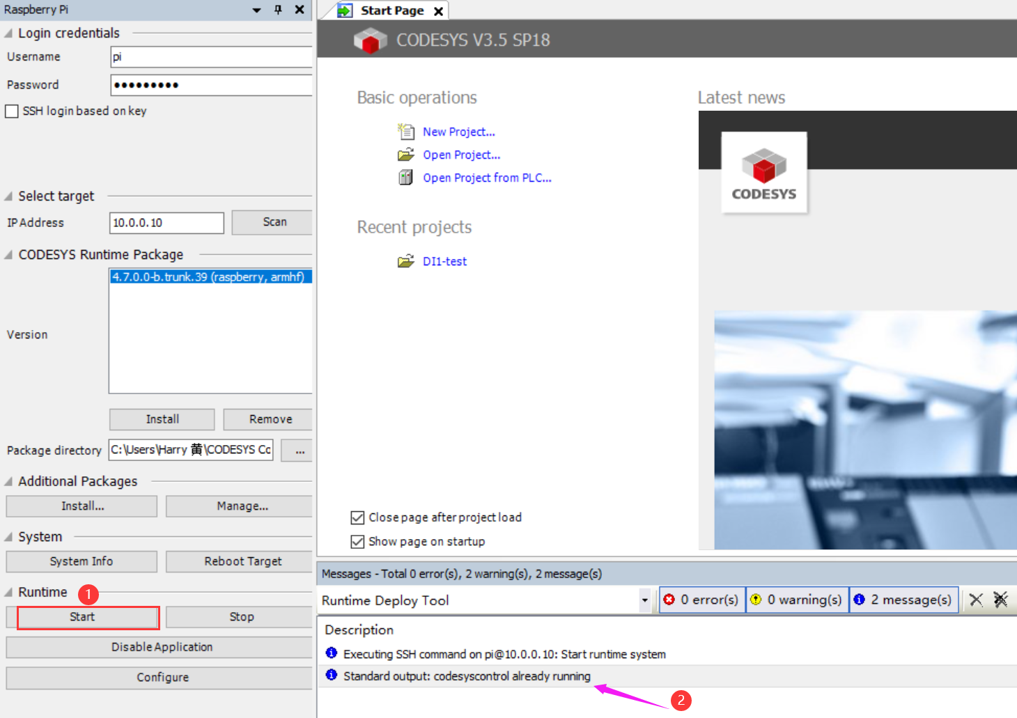
- 2.4 Confirm the “CODESYS Control for Raspberry Pi runtime” is running on “EG500”.
Click “Start” at the “Runtime” section, and then check the “Messages” windows state that “Standard output: codesyscontrol already running”
3. Create a project that trigger light control by DO port.
- 3.1 Project Setup.
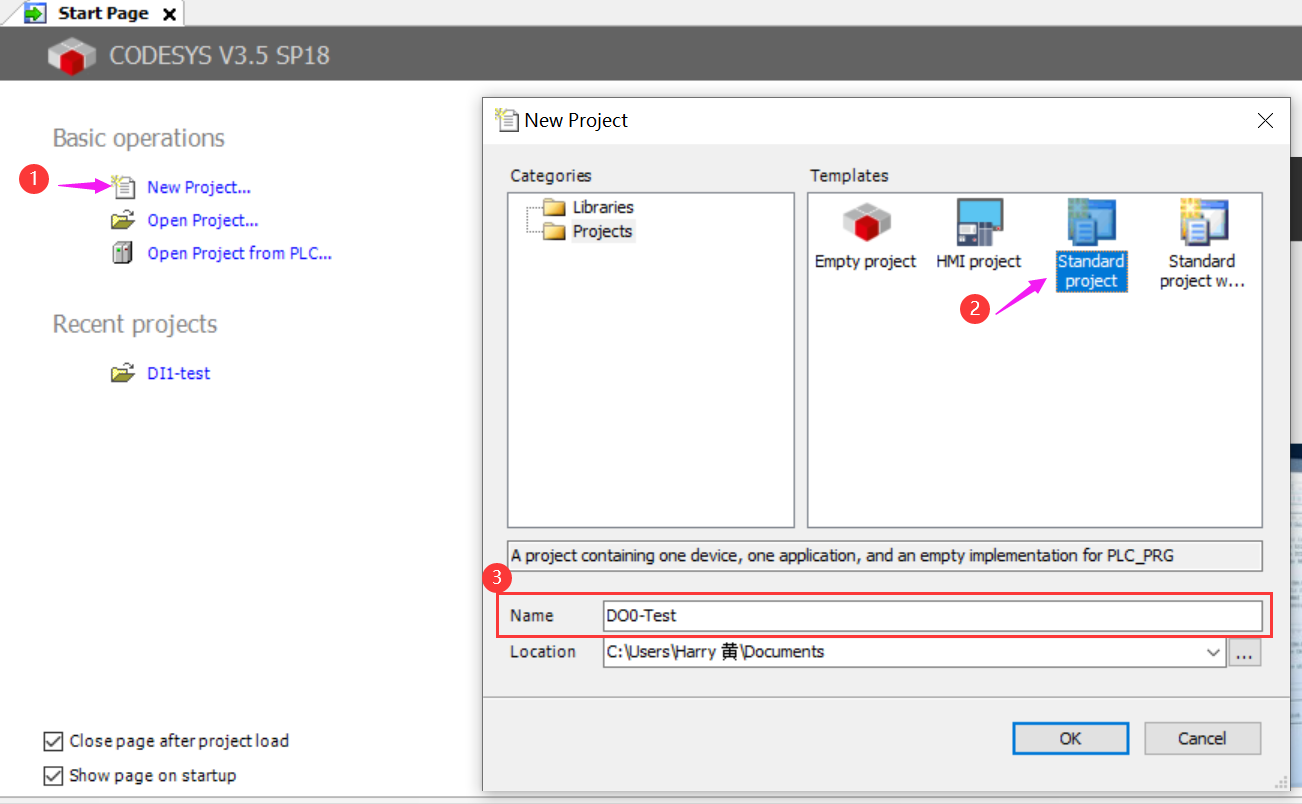
Open the CODESYS Development System V3 software and select “File>New Project…” or click “New Project…” on Basic operations menu.
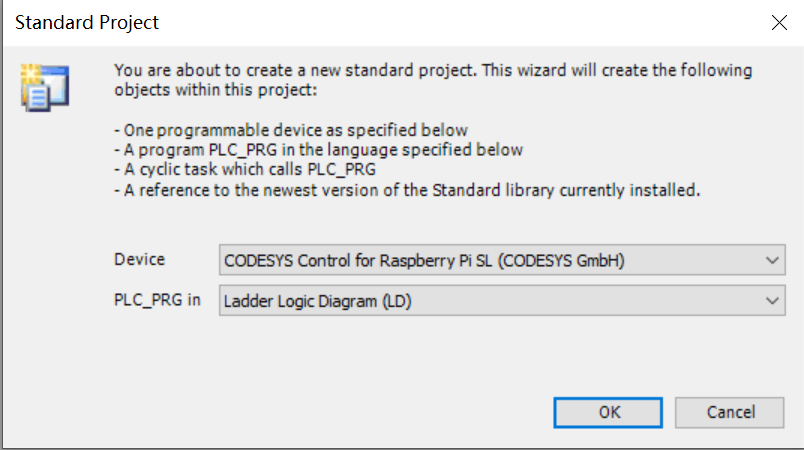
In this demo, we created a “Standard project” in templates, and named it “DO0-Test”, Click OK.
- 3.2 At the Standard Project Window, select “CODESYS Control for Raspberry Pi SL (CODESYS GmBH)” for device, and for PLC_PRG in select “Ladder Logic Diagram (LD)”, then click “OK”.
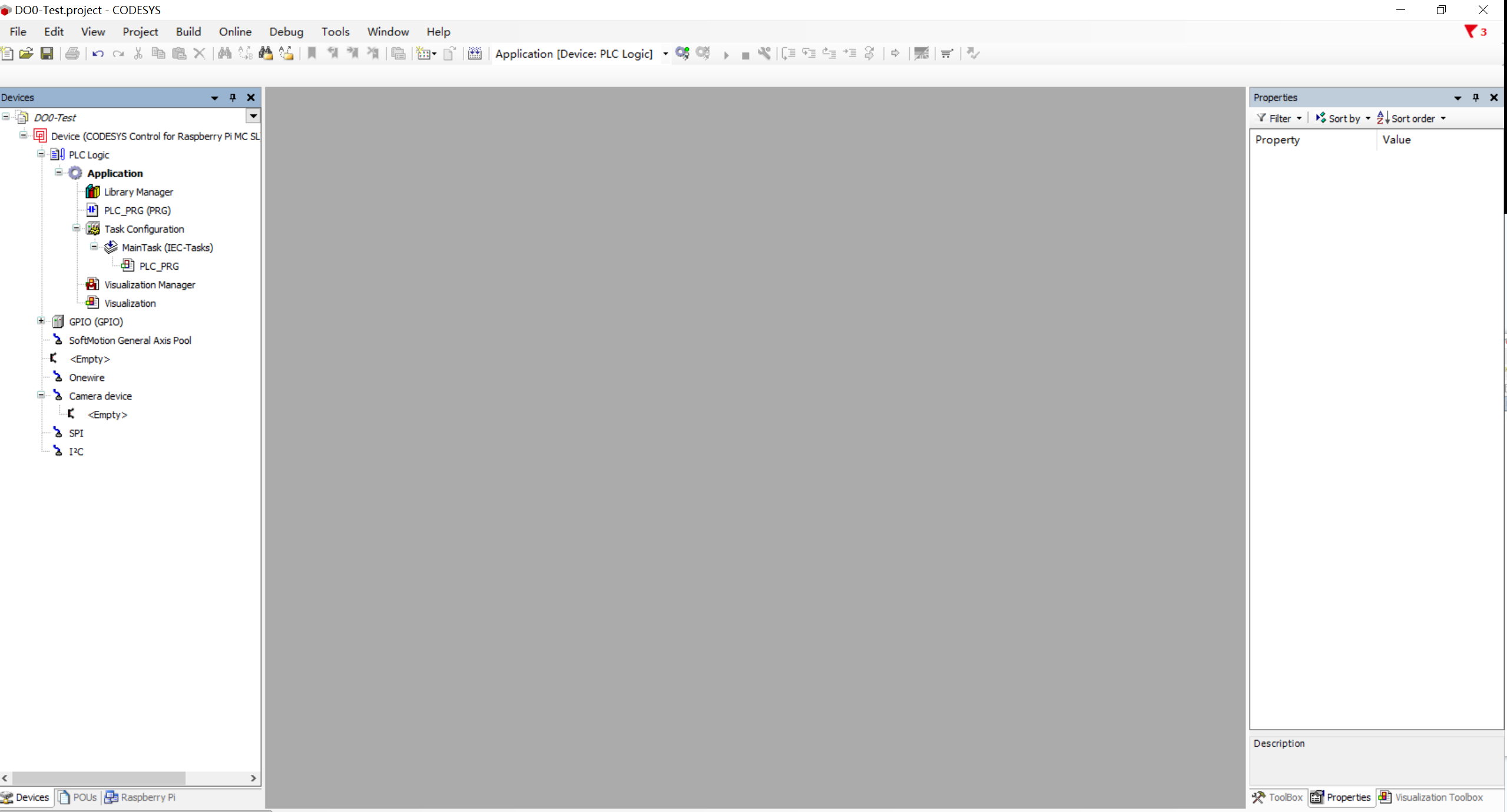
A typical user interface you should get after success setup a new project on Codesys IDE.
4. Program and Configure the project
- 4.1 Create variables and elements for this project.
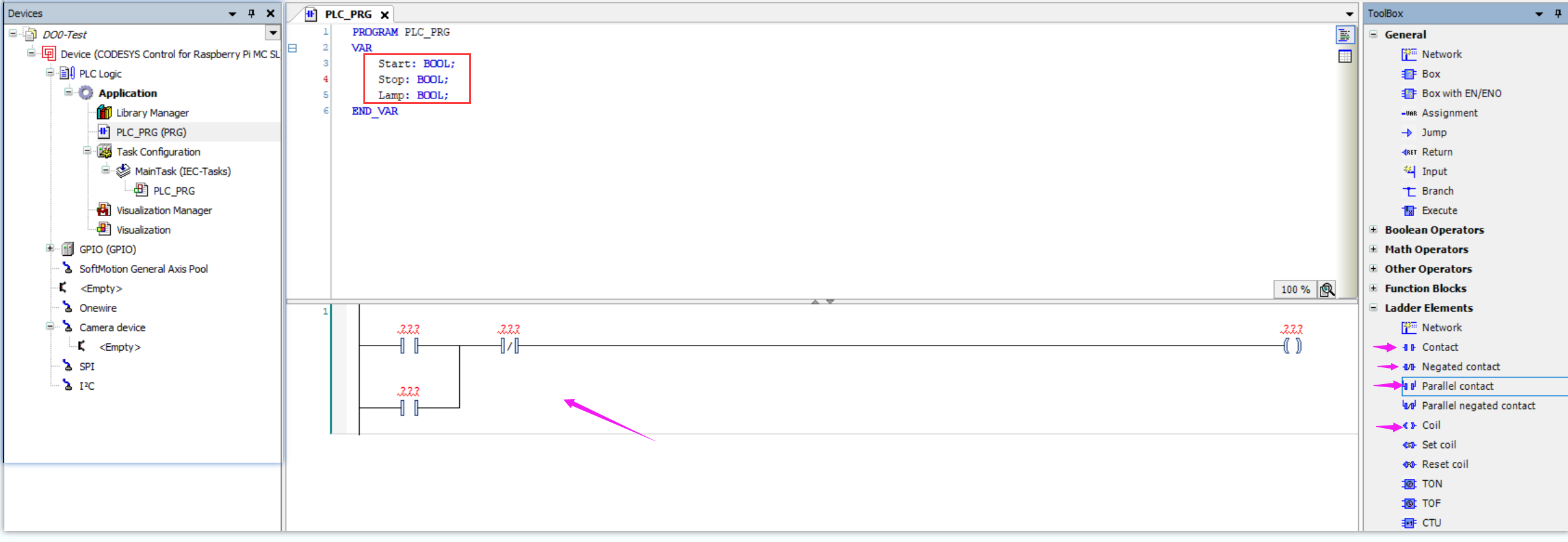
Double click the “PLC_PRG” tab at the left column menu, on PLC_PRG program page, create three variables that “Start”, “Stop” and “Lamp” as BOOL type.
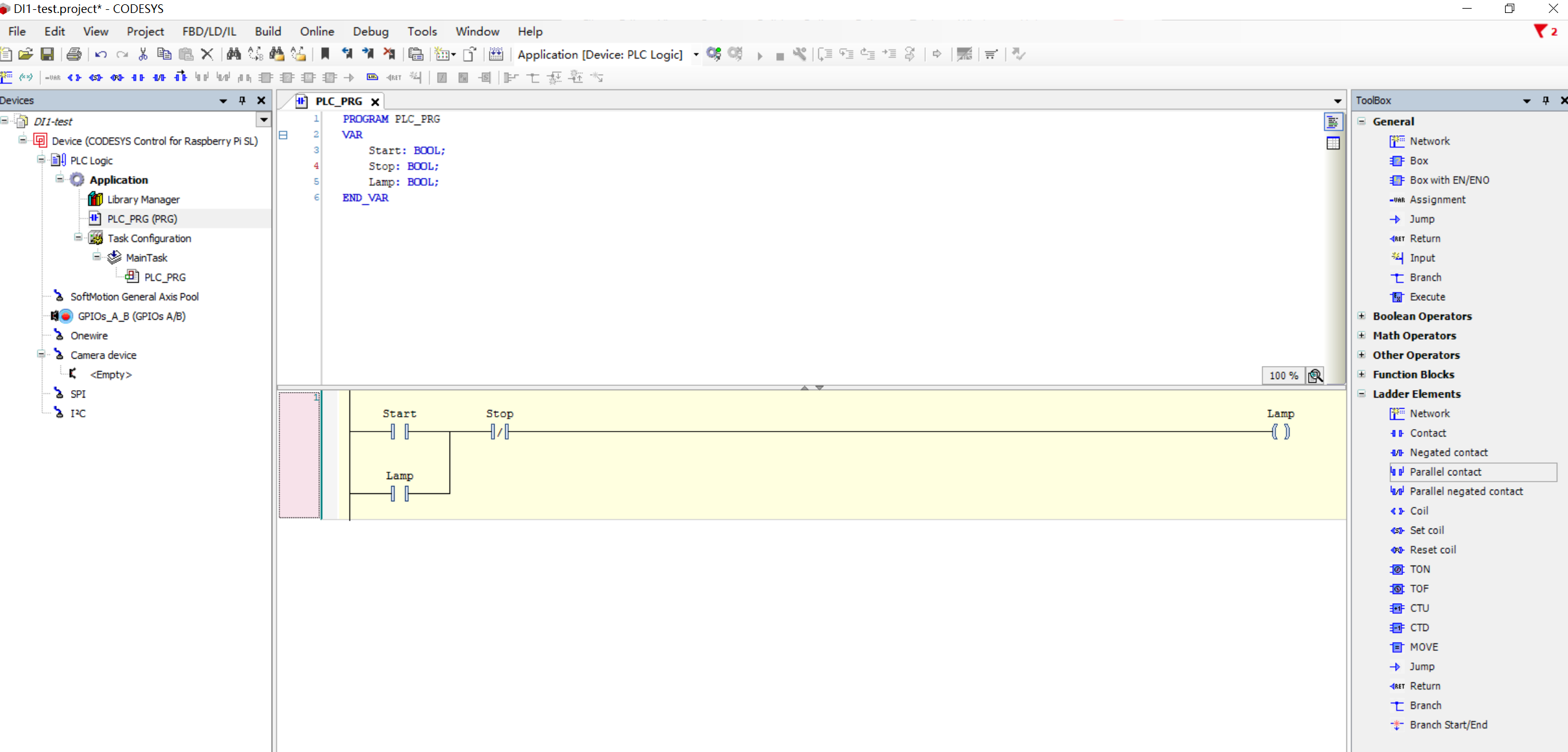
And add Ladder Elements “Contact”, “Negated contact”, “Parllel contact”, and “Coil” items from right column ToolBox menu.
- 4.2 Configure the variable for each elements.
Click the “???” symbol upon element and “…” button, select the relevant variable in pop-up window. In this case,
Assign “Start” variable for “Contact” element,
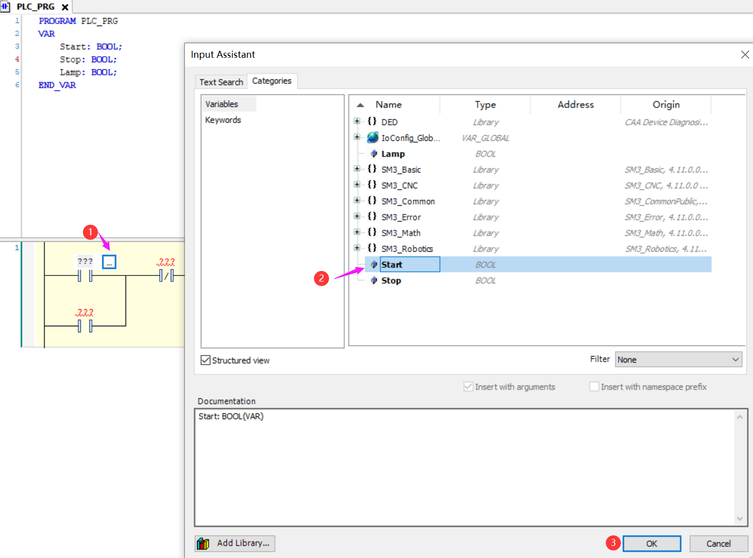
Assign “Stop” variable for “Negated contact” element.
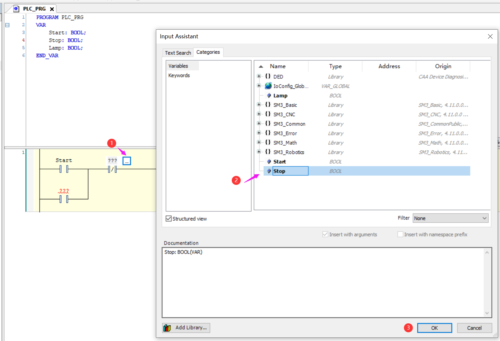
Assign “Lamp” variable for “Parallel contact” and “Coil” elements.
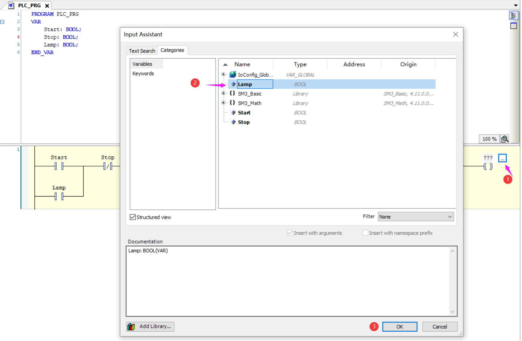
The completed settings would like below screenshot.
- 4.3 Add GPIO device.
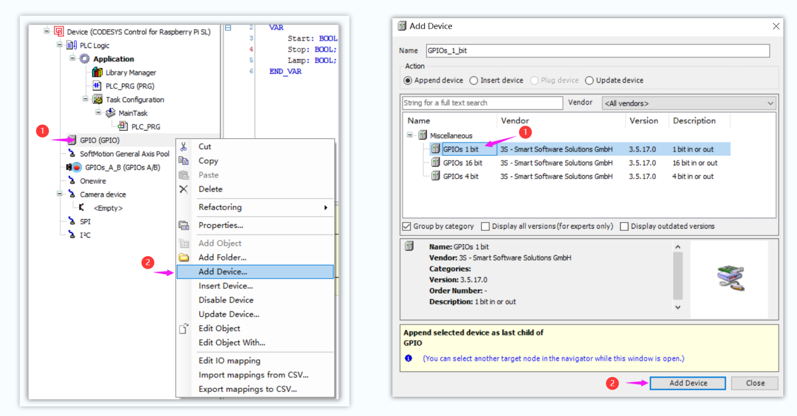
Select and right click “Device” tab at left column menu, -> “Add Device…”, on pop-up window, “Miscellaneous” -> “GPIO”, and click “Add Device” button.
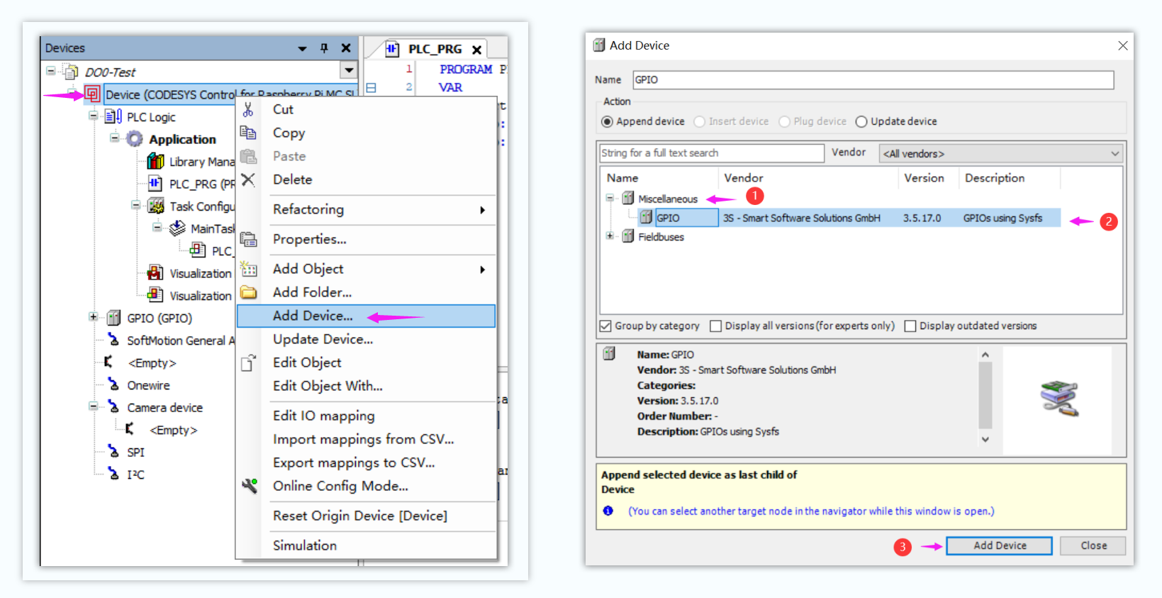
The “GPIO (GPIO)” device will be added on the device tab list.
Right click GPIO to add 1 bit GPIO device. Following steps like “Add Device…” -> “Miscellaneous” -> “GPIOs 1 bit”, then click “Add Device” button.
- 4.4 Configure the GPIO device.
Double click “GPIOs_1_bit (GPIOs 1 bit)” tab to open the GPIO setting page.
At first tab “GPIOSysfsModuleParameters”, config and assign the GPIO Direction, Pin Number and current PIN state.
In this case we will rely DO0 port on EG500 to toggle the Light on/off, which the DO0 port GPIO Pin number would be 22 according to EG500 admin guide.
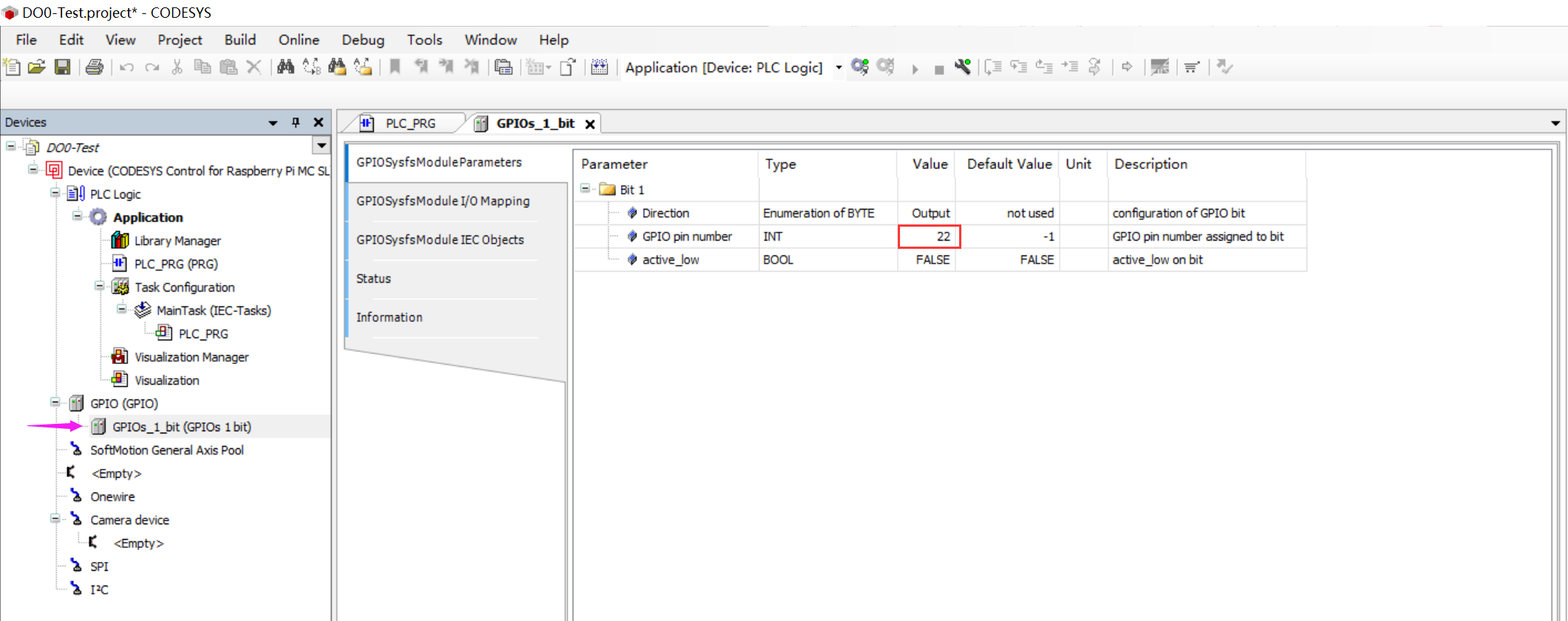
While on EG410, we will use DO1 port to toggle the light, which the DO1 GPIO Pin number would be 24,

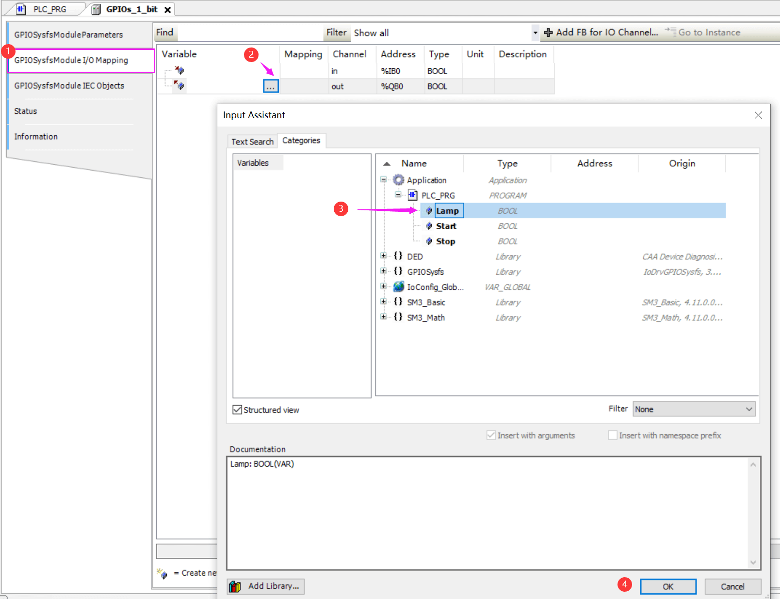
At tap “GPIOSysfsModule I/O Mapping”, assign the variable “Lamp” to GPIO out channel.
The operating steps like below screenshot.
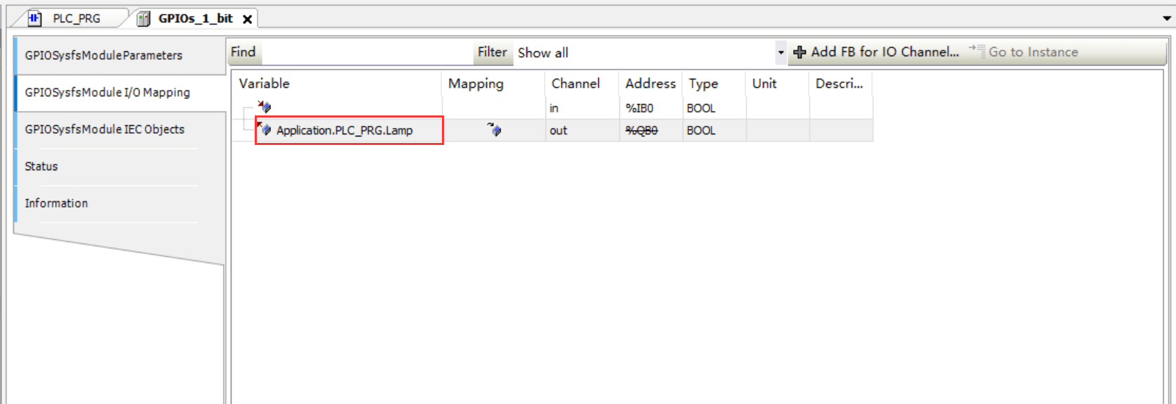
After finished the GPIO configuration, CTRL+S save the settings.
- 4.5 Create Visualization UI for this project
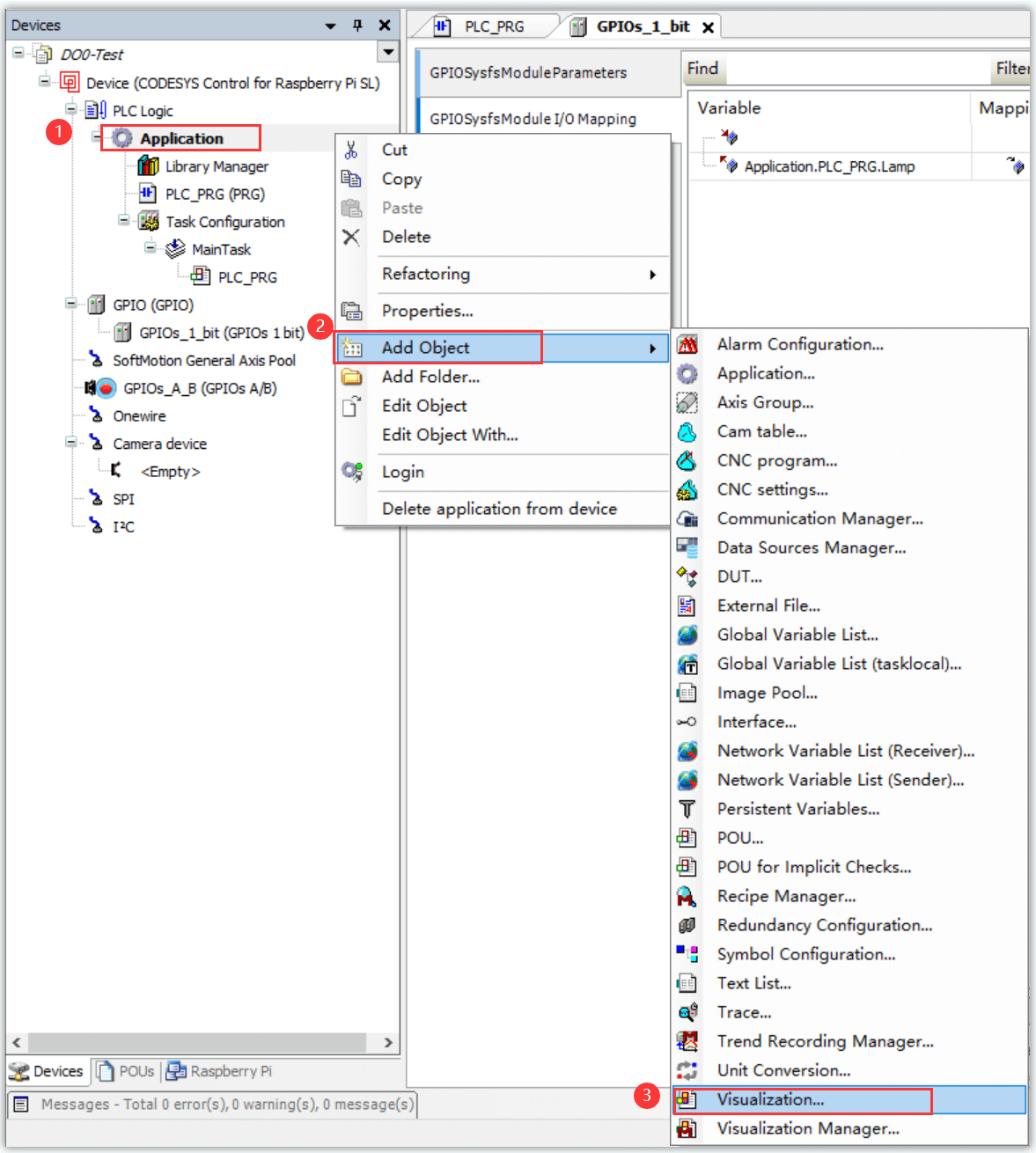
Right click the Application tab in left column menu,
Following Application -> Add Object -> Visualization…, like below screenshot.
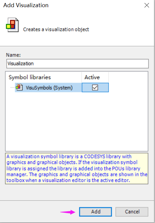
Active VisuSymbols (System) and “Add”,
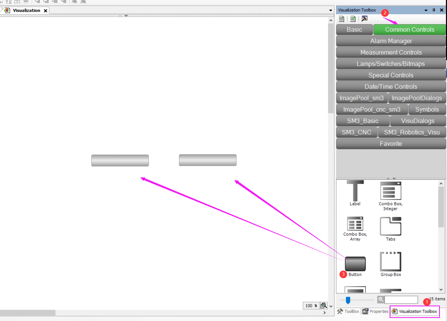
Add two Buttons and a Lamp on Visualization configuration page to simulate and operate the Lamp light on and off.
Click “Visualization Toolbox” tab at the bottom of right column, drag and drop two “Button” from “Common Controls” section,
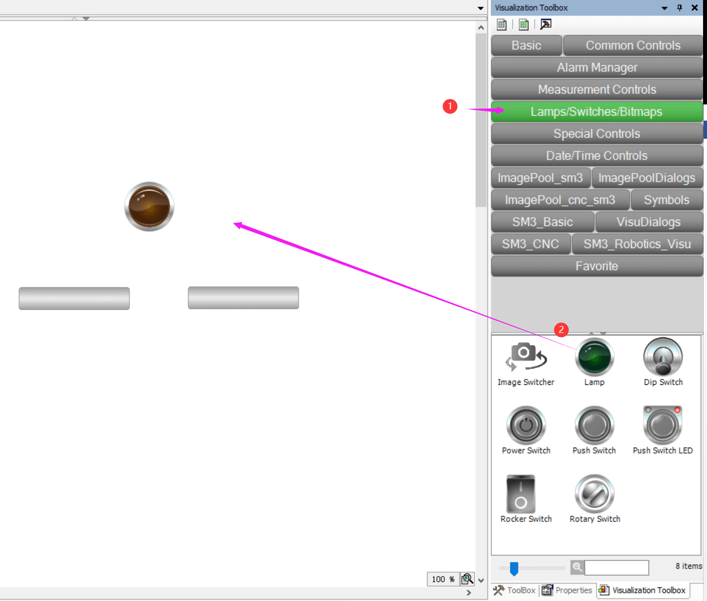
And drag and drop a “Lamp” from “Lamps/Switches/Bitmaps” section,
- 4.6 Configure the Visualization
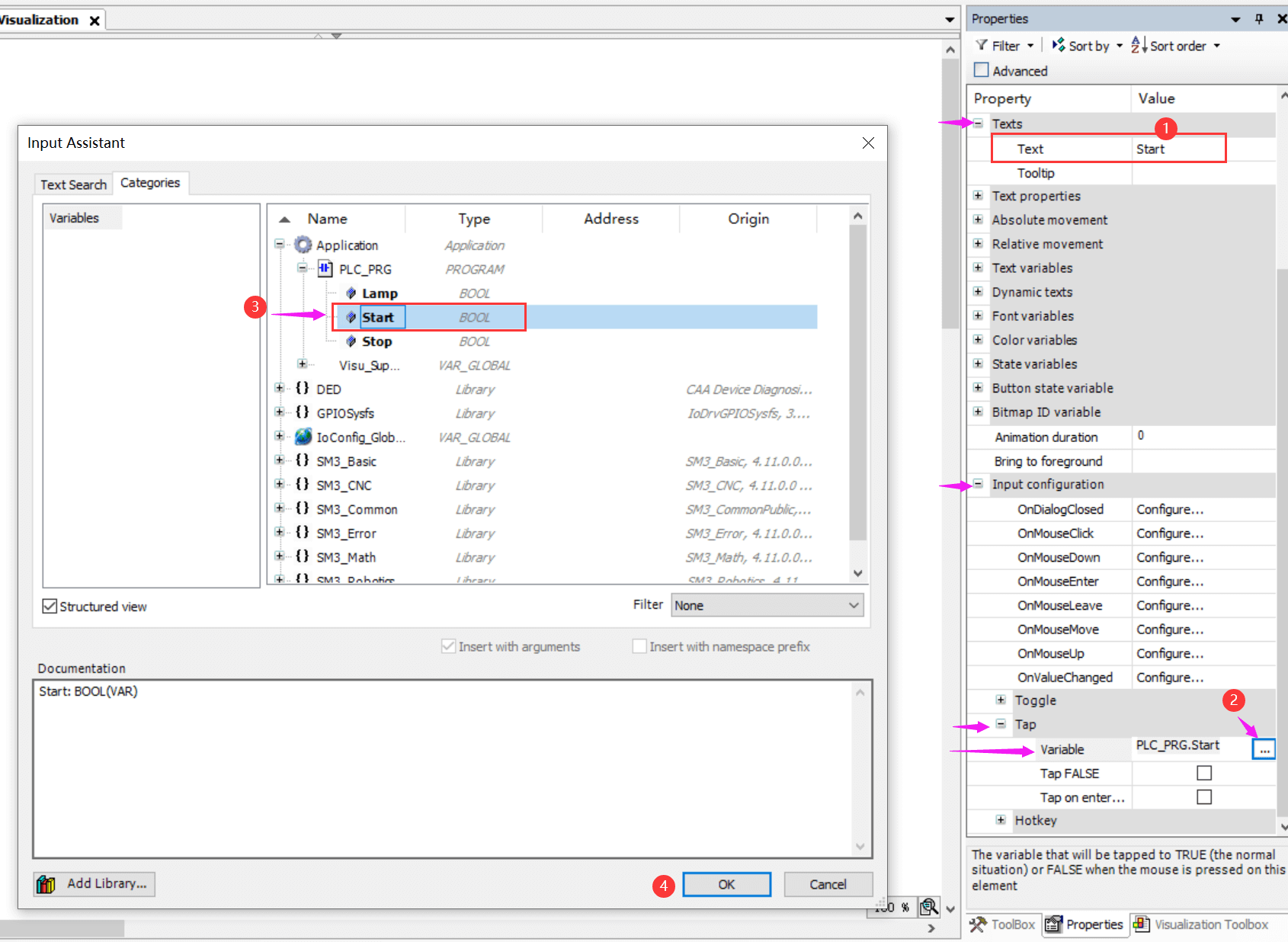
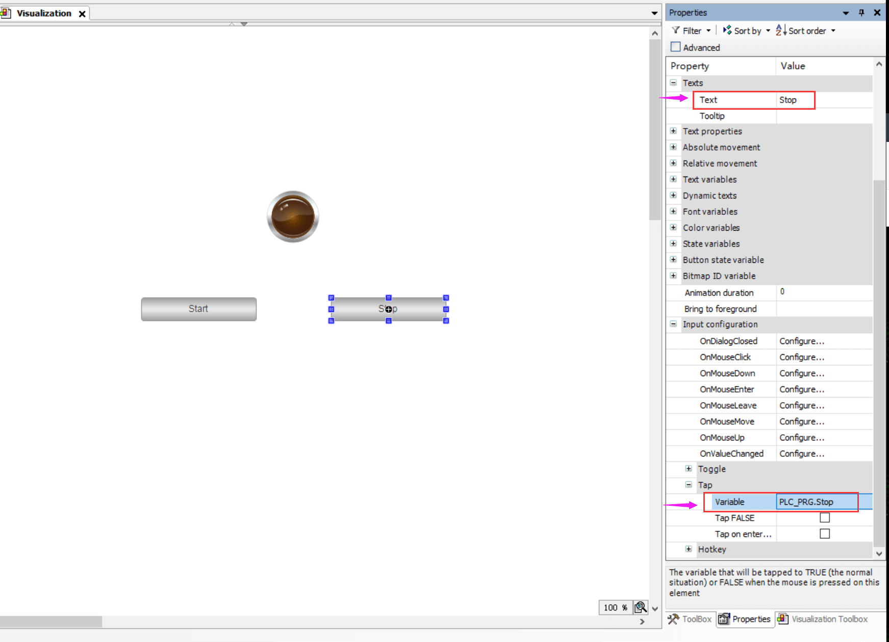
Config the Buttons name on Text value at “Property” -> “Texts” -> “Text”.
And assign its variable from “Property” -> “Input Configuration” -> “Tap” -> “Variable”.
In this case, the left button will be named “Start”, and assigned variable “Start”, operating steps like below screenshot,
The right button will be named as “Stop”, and assigned variable “Stop”, like below screenshot,
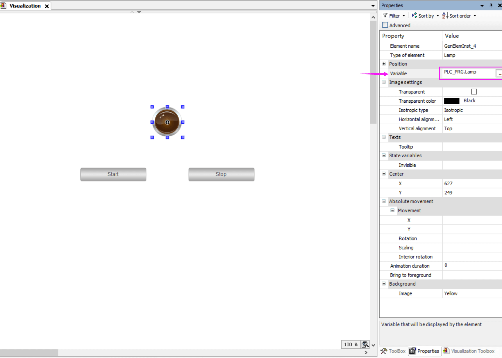
The Lamp symbol will be assigned variable “Lamp”, like below screenshot,
After finished the Visualization configuration, CTRL+S to save the project.
5. Compile and Run the project programs on Device
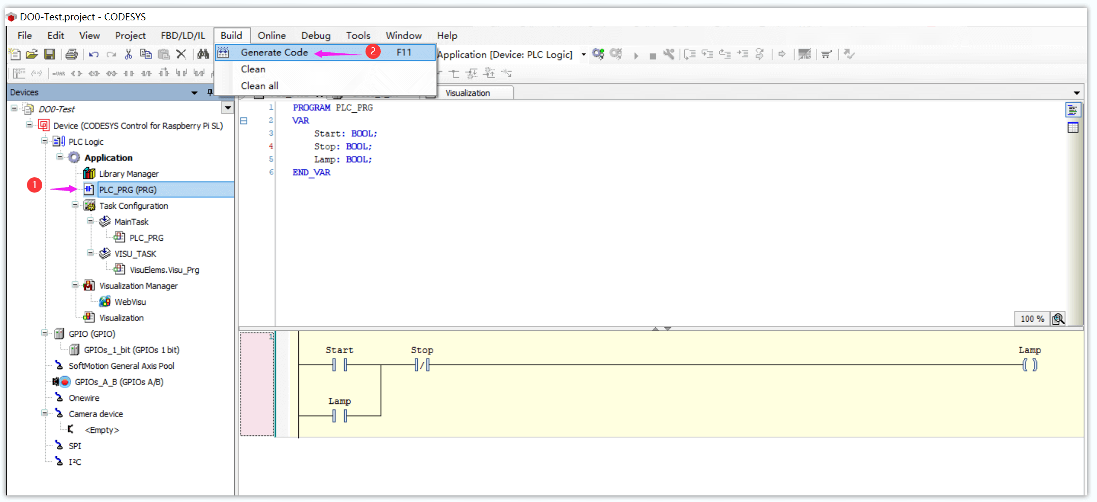
- 5.1 Click menu “Build” -> “Generate Code”. To compile the project programs.
- 5.2 Connect and download the project code to EG500
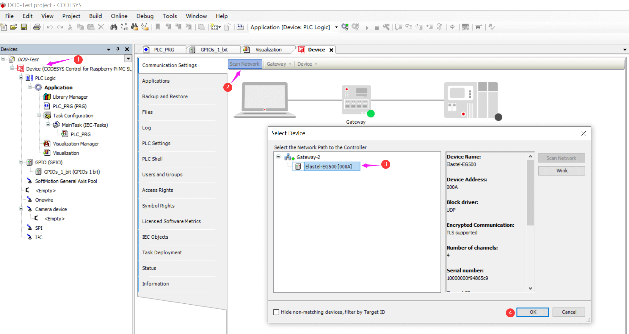
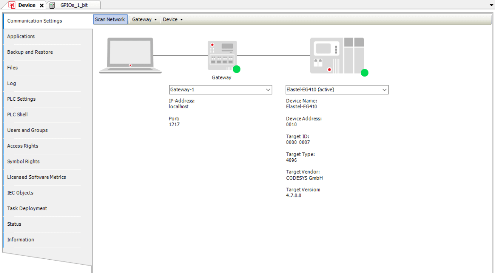
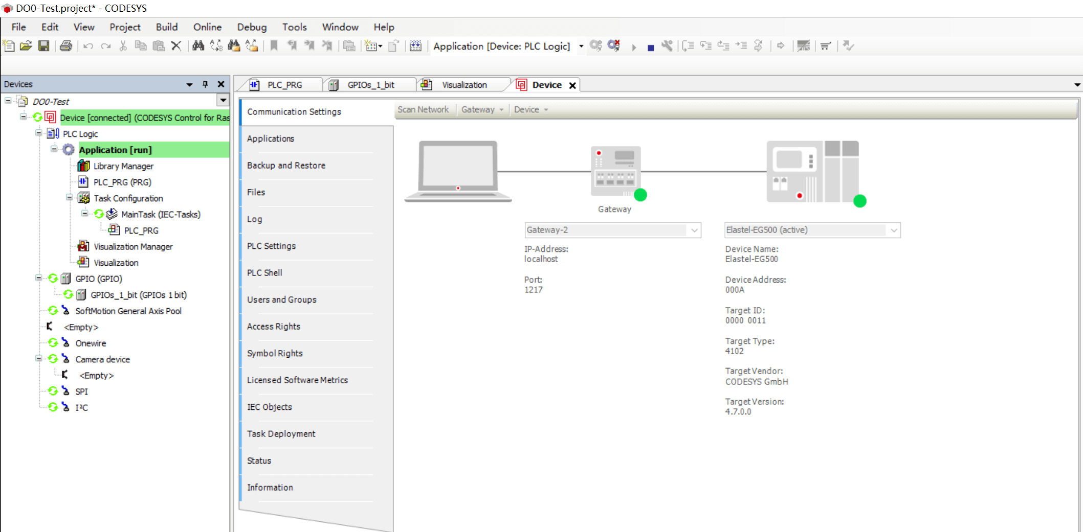
Double click the “Device” tab in left column menu, click “Scan Network” to search the device you are operating, in this case, select the found device “Elastel-EG500” to connecting.
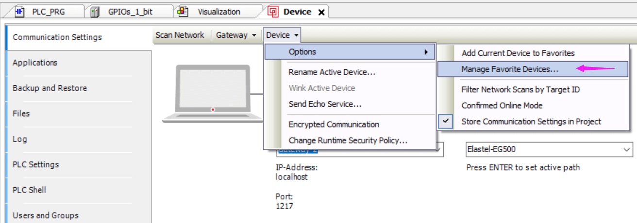
You can also manually add the device with its IP address in case you knew it.
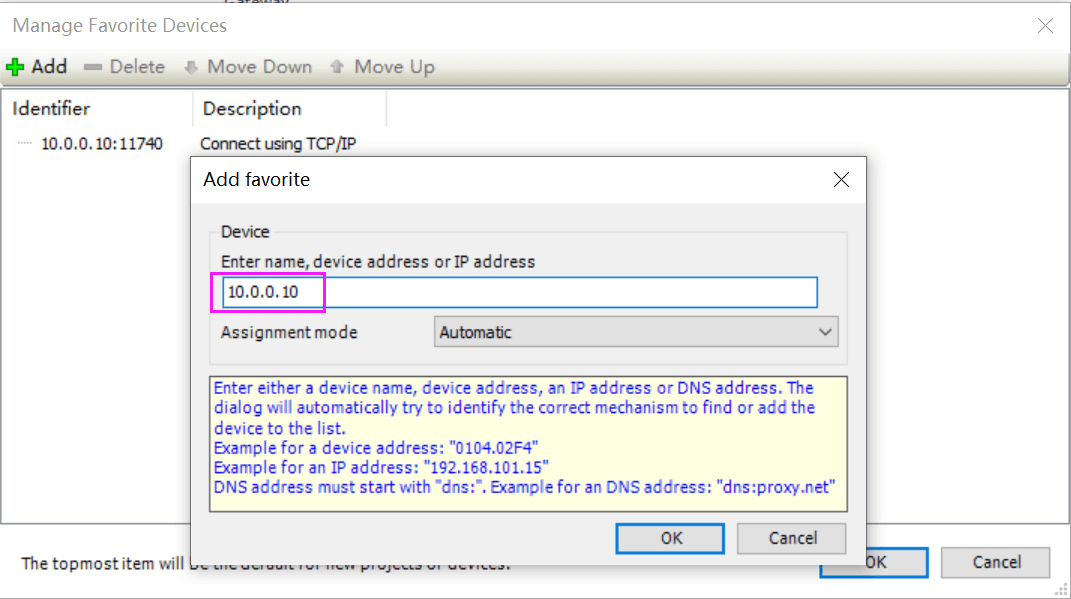
Following steps “Device >> Options >> Manage Favorite Devices… >> Add”, then input the device IP address (in this case the EG500 IP address is 10.0.0.10).
It will ask you input the login credentials username password when connecting to device.
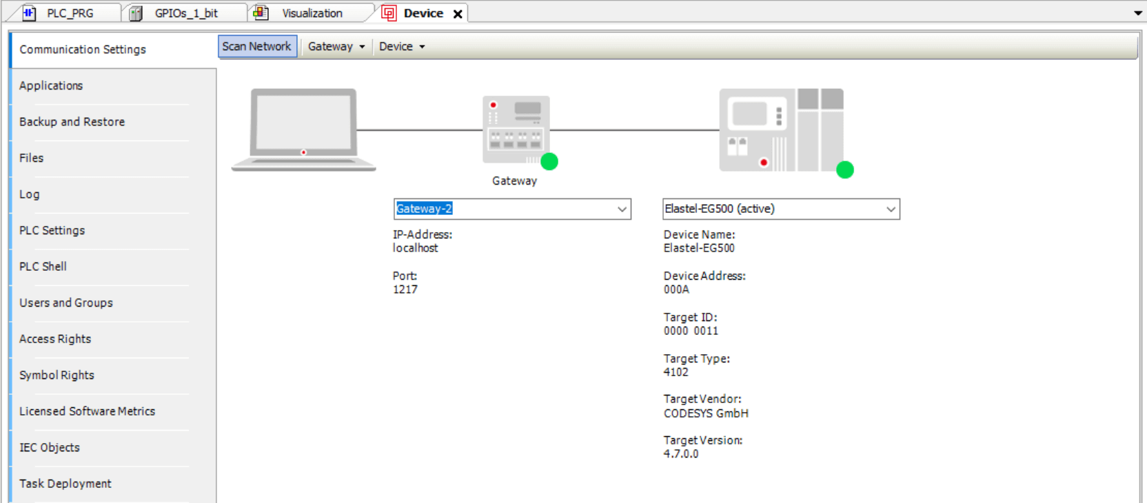
The below screenshot shows the device (Elastel-EG500) was successfully connected.
- 5.3 Click menu “Online >> Login” to login and download the project to device,

Press F5 to run the project on device.
Application Demonstration
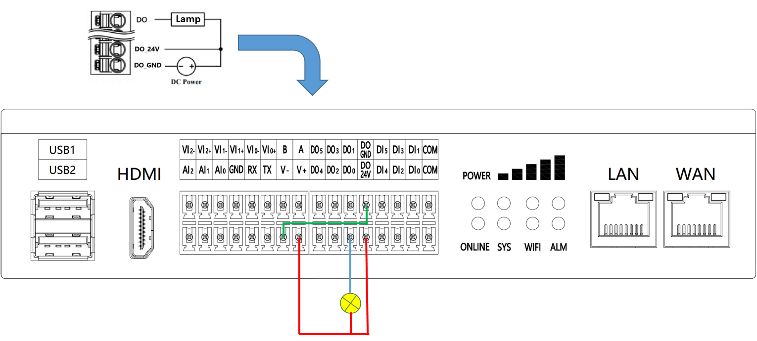
- Wiring
On EG500, we rely on the DO0 port to perform the light control, and the V-, V+ power output ports will be used as DC Power for Lamp. The wiring would like,
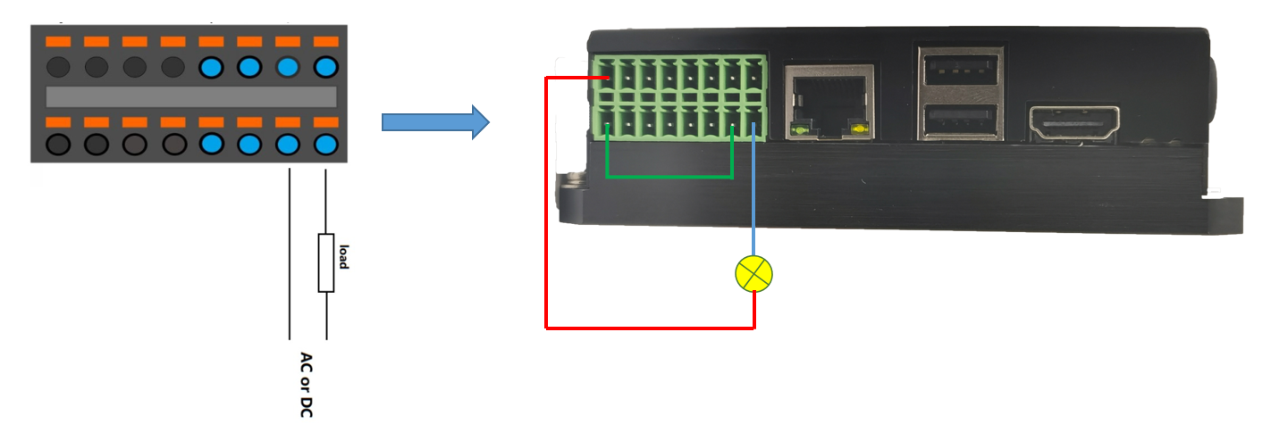
On EG410, we rely on the DO1 port to perform the light control, and bridge the power supply ports as DC power for Lamp. The wiring would like,
- Demonstration
Test operation on EG500
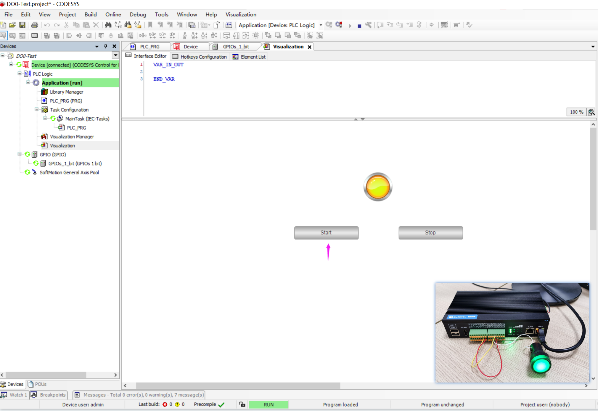
When project status running, on Visualization page, click “Start” button, the Lamp on visualization will be turned on, meanwhile the light wiring on EG500 will be turned on as well. Like below test result recording,
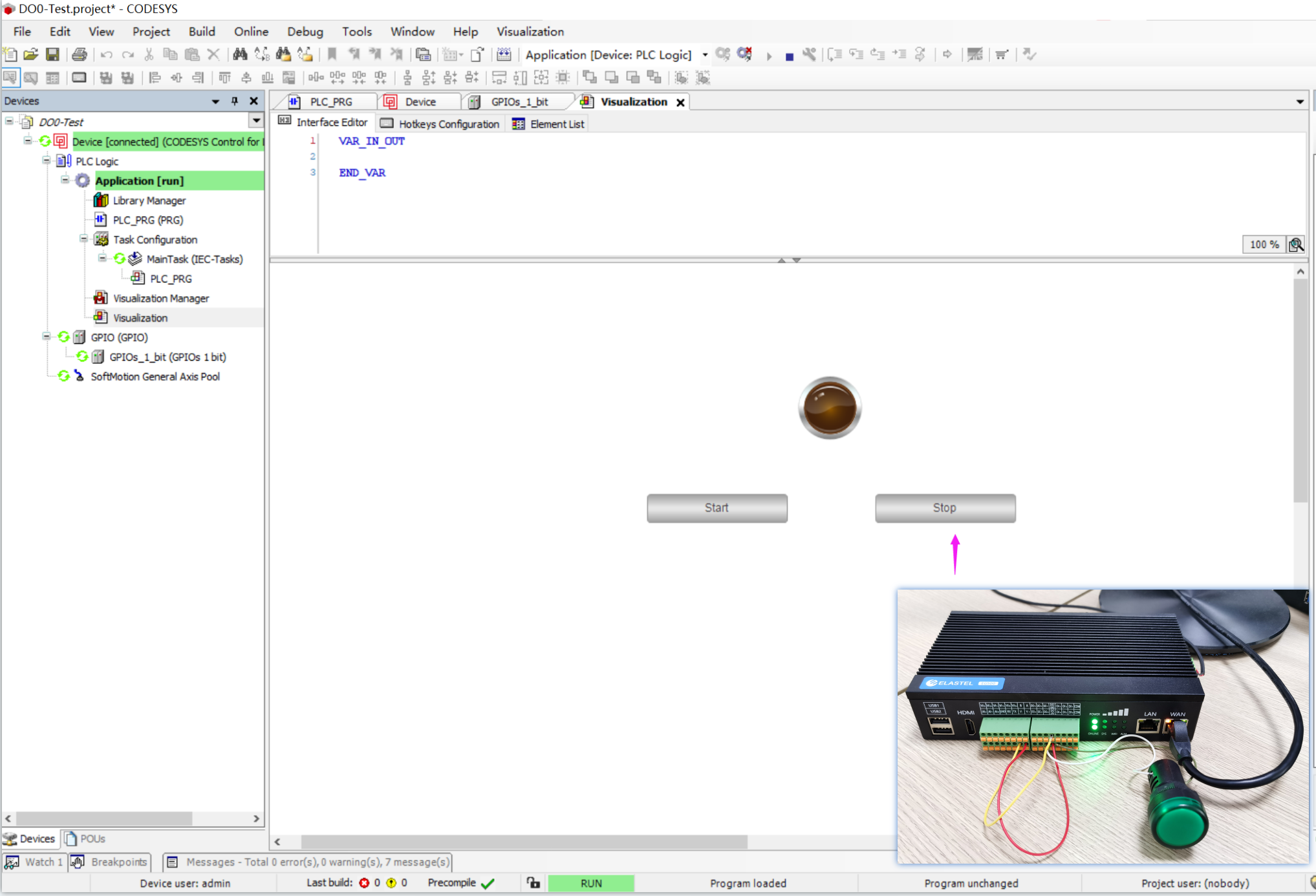
When click “Stop” button, the Lamp will be light off at same time both in visualization and EG500 side, as below test result recording.
Test operation on EG410
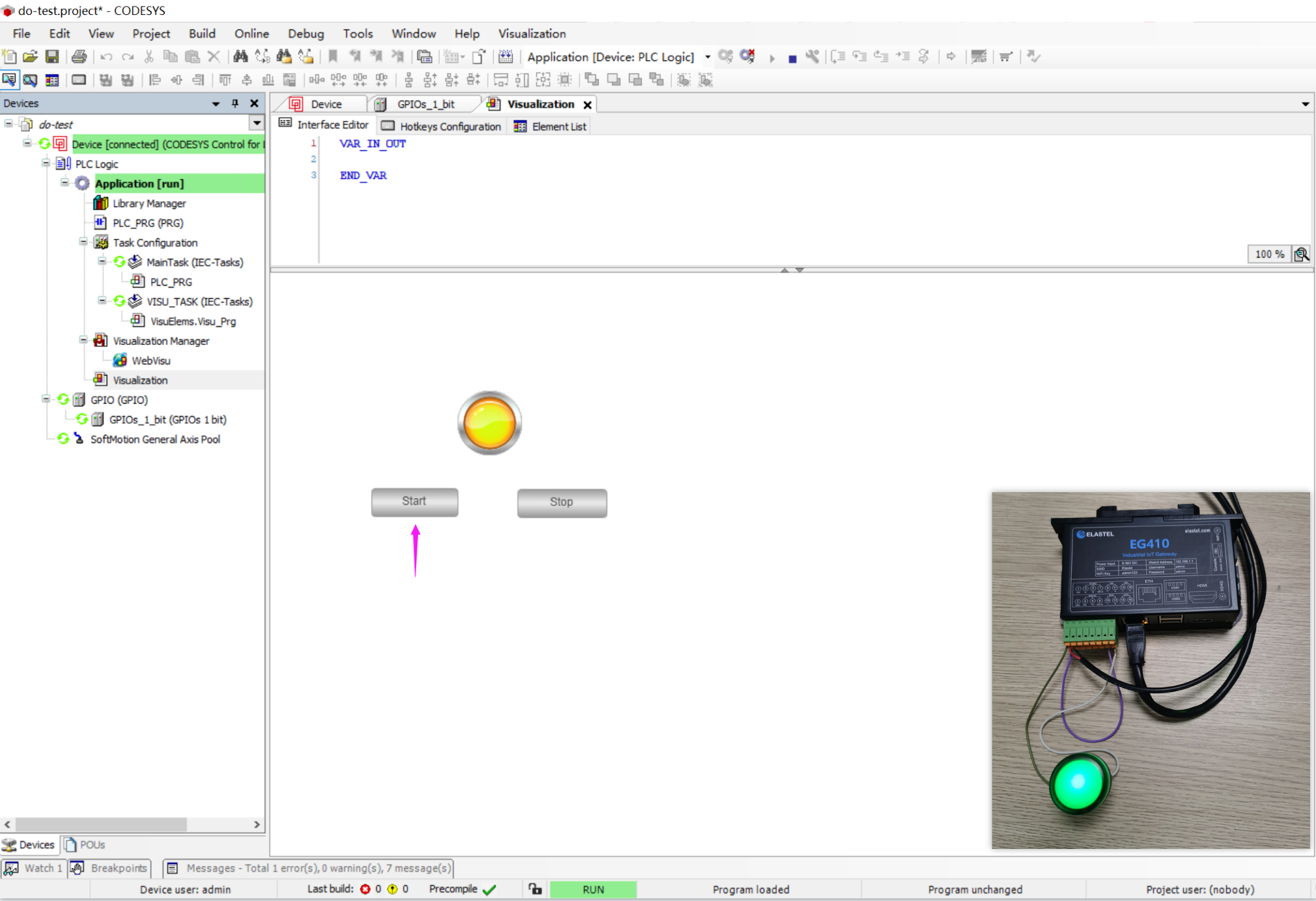
When click “Start” button, the Lamp will be light on at same time both in visualization and EG410 side, as below test result recording.
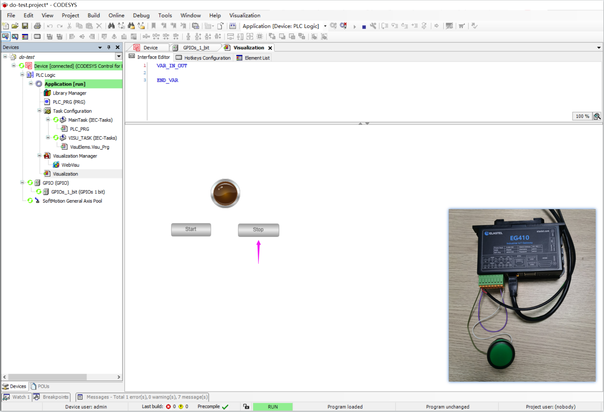
When click “Stop” button, the Lamp will be light off at same time both in visualization and EG410 side, as below test result recording.
- WebUI
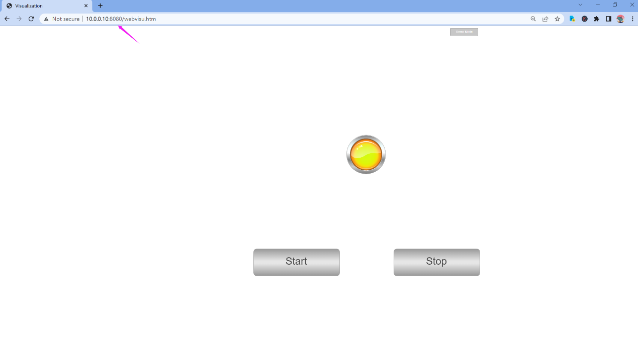
You can also operate the Visualization UI from web by accessing the IP address of EG500/EG410 device, with the 8080 port, like http://10.0.0.10:8080, as below test result recording.
Above demo conclude that CODESYS system is perfect compatibly running on Elastel industrial Raspberry Pi series products for your industrial applications.
Please contact with Elastel sales engineers [email protected] for more Raspberry Pi solutions on Elastel industrial Raspberry Pi products.

